


Revit MEP Complete Beginner Guide 2026: Master Mechanical, Electrical, and Plumbing Design
What is Revit MEP? Complete Overview for Beginners | s2bschoolofengineering
Revit MEP is Autodesk's specialized Building Information Modeling (BIM) software designed for engineers and designers to create intelligent 3D models of building mechanical, electrical, and plumbing systems. Unlike traditional 2D CAD approaches, Revit MEP uses parametric components, automated system connections, and real-time coordination to ensure accurate design and documentation. This beginner's guide covers essential MEP skills—HVAC design, ductwork layout, electrical system modeling, plumbing configuration, and clash detection. With over 68+ Revit MEP job openings across India and growing BIM adoption in construction, learning Revit MEP in 2026 opens career opportunities as MEP coordinators, BIM managers, and design engineers earning ₹15,000 to ₹80,000 monthly. Whether you're a mechanical engineer, civil designer, or aspiring BIM professional, mastering Revit MEP provides industry-ready skills that directly connect to employment in airports, data centers, hospitals, and large-scale construction projects. S2B School of Engineering offers comprehensive MEP design courses combining hands-on BIM training with mechanical, electrical, and plumbing systems expertise
Why Learn Revit MEP in 2026?
The construction industry has fundamentally shifted toward BIM workflows. Revit MEP is now the industry standard for:
- Accurate System Design: Creating HVAC, electrical circuits, and plumbing networks with automatic calculations
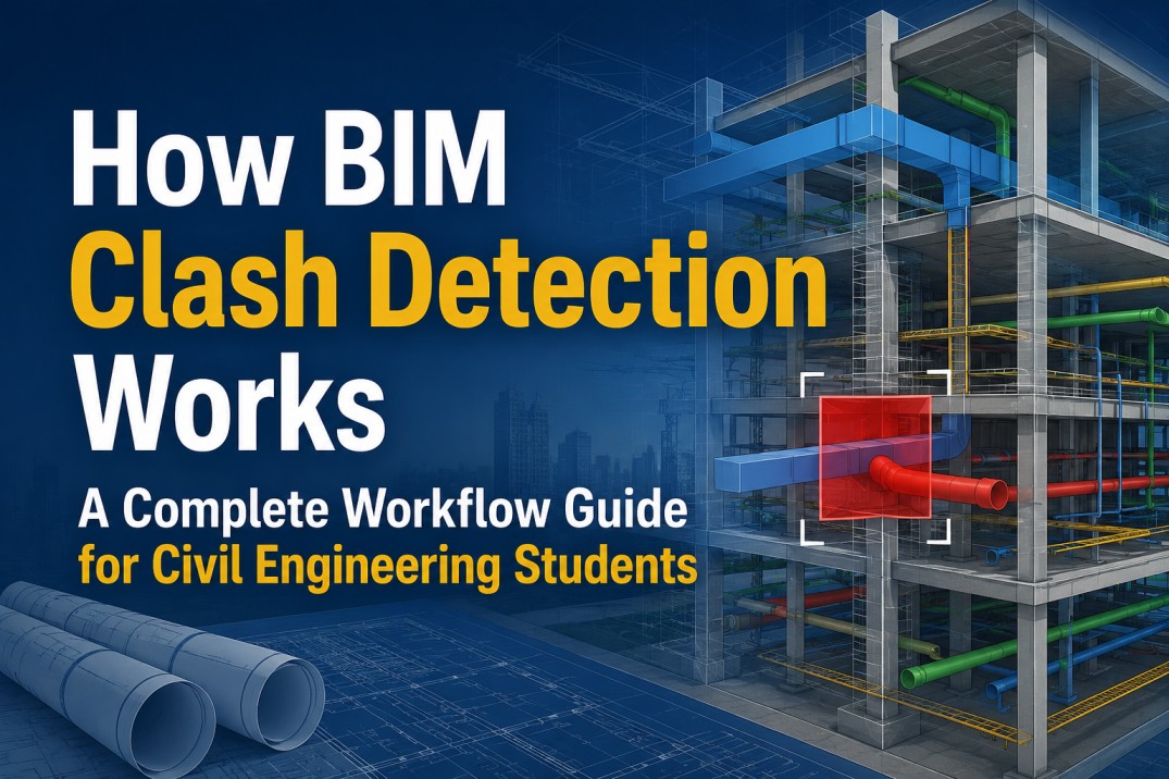
- Clash Detection: Identifying conflicts between systems before construction begins, reducing costly on-site rework
- Collaborative Workflows: Enabling architects, structural engineers, and MEP teams to work on a unified digital model
- Documentation Automation: Generating schedules, panel layouts, and shop drawings directly from the model
- Cost Efficiency: Reducing design time by 30-40% compared to traditional CAD methods
Understanding MEP: The Three Core Disciplines
Mechanical (HVAC) Systems
Mechanical systems handle heating, ventilation, and air conditioning for optimal indoor climate control. In Revit MEP, you’ll work with:
- Air Handling Units (AHUs): Central equipment that conditions and distributes air
- Ductwork: Supply, return, and exhaust ducts that route air throughout the building
- Air Terminals: Diffusers, grilles, and registers that deliver or extract air
- Accessories: Fire dampers, volume control boxes, and silencers that ensure safety and performance
Key Concept: HVAC systems must be properly sized to match airflow requirements and routed to avoid conflicts with structural elements and other MEP systems.
Electrical Systems
Electrical systems provide power distribution, lighting, and control circuits throughout buildings. Core components include:
- Power Panels: Distribution boards that manage electrical circuits and loads
- Lighting Fixtures: Recessed, surface-mounted, and suspended fixtures for illumination
- Receptacles & Switches: Outlets and control devices for electrical equipment
- Circuiting: Connections from fixtures to panels with load balancing
- Panel Schedules: Automated documentation showing circuit descriptions, breaker types, and loads
Key Concept: Electrical design requires proper load calculation, circuit organization, and coordination with HVAC equipment connections for seamless integration.
Plumbing & Sanitary Systems
Plumbing systems manage water supply, drainage, and gas distribution. Essential components include:
- Domestic Water Supply: Hot and cold water lines from mains to fixtures
- Sanitary Drainage: Waste and vent piping that manages fixture drainage
- Fixtures: Sinks, toilets, showers, and other connection points
- Piping Accessories: Valves, strainers, pressure-reducing devices, and traps
- Slope Management: Critical for gravity-fed drainage systems
Key Concept: Sanitary piping requires proper slope (typically 1/4” per 1 foot) to ensure gravity-driven flow and prevent backup.
Getting Started: Revit MEP Project Setup
Step 1: Choose the Correct MEP Template
Begin every Revit MEP project by selecting the appropriate template:
Available Templates: - Mechanical Template: For HVAC design and ductwork - Electrical Template: For power systems, lighting, and circuits - Plumbing Template: For water supply and sanitary drainage - MEP Coordination Template: For multi-discipline projects
These templates come pre-configured with appropriate view types, schedules, and annotation standards aligned with industry best practices.
Step 2: Configure Project Units and Settings
Standardize your project units for consistency:
Mechanical Settings (Systems Tab > Mechanical Settings): - Duct sizing units (typically inches) - Pipe sizing units (typically inches) - Flow units (CFM for air, GPM for water) - Pressure units (inches of water column)
Electrical Settings (Manage > Electrical Settings): - Voltage standards (120/240V for residential, 208/277V for commercial) - Wire gauge and conduit sizing - Grounding requirements
Step 3: Link Architectural and Structural Models
MEP design must align with architectural layouts and avoid structural conflicts.
Linking Process: 1. Go to Insert Tab > Link Revit 2. Select the architectural model file 3. Set positioning to Auto - Internal Origin to Internal Origin (ensures all disciplines align) 4. Repeat for structural model if coordination is required
Why Link?: This creates a reference model that ensures your MEP components sit correctly within building spaces without floating or penetrating walls unexpectedly.
Step 4: Copy and Monitor Levels and Grids
Synchronize levels and grids from the linked architectural model:
- Navigate to Collaborate Tab > Copy/Monitor
- Select levels and grids from the linked model
- Place them in your MEP project
- Use Monitor to track changes—if the architect modifies a level height, Revit alerts you to update your MEP design
Benefit: This automated coordination prevents misalignment between disciplines, reducing coordination errors by up to 60%.
Step 5: Set View Range and Create Views
Define what elements appear in each view:
- View Range: Controls vertical slice (e.g., showing elements between 0-14 feet on a floor plan)
- Visibility Settings: Toggle MEP systems on/off by discipline
- View Templates: Standardized view configurations for consistency across the project
HVAC System Design in Revit MEP: A Complete Workflow
Understanding HVAC System Basics
An HVAC system consists of equipment (AHU), ductwork, air terminals, and accessories working together to condition and distribute air.
System Types in Revit: - Supply Air: Delivers conditioned air to spaces - Return Air: Extracts used air from spaces - Exhaust Air: Removes air from kitchens, bathrooms, and mechanical rooms
Creating HVAC Systems Step-by-Step
Phase 1: Place Mechanical Equipment
- Navigate to Systems Tab > Mechanical Equipment
- Select an air handling unit (AHU) from the Type Selector
- Place the equipment in the mechanical room (typically in the basement or rooftop)
- Verify elevation and placement in 3D view to confirm clearances
Pro Tip: Always place AHUs in dedicated mechanical rooms with adequate space for maintenance access.
Phase 2: Place Air Terminals
Air terminals (diffusers, registers, grilles) are connection points where conditioned air enters or exits spaces.
Process: 1. Go to Systems Tab > Air Terminal 2. Select terminal type (supply diffuser, return grille, exhaust cap) 3. Place terminals strategically: - Supply: Near ceiling or high walls for even distribution - Return: Lower on walls to capture warm/stale air - Exhaust: Exterior walls for moisture-heavy areas (kitchens, bathrooms)
Spacing Calculation: Maintain adequate separation between supply and return terminals to prevent short-circuiting (air returning immediately after supply without conditioning the space).
Phase 3: Generate Duct Systems Automatically
Revit MEP automates duct routing using the Generate Layout feature:
Workflow: 1. Select all air terminals and mechanical equipment for one system 2. Go to Modify Tab > Multi-Select > Create System 3. Choose system type (Supply Air, Return Air, etc.) 4. Under Systems Tab > Duct System > Generate Layout 5. Configure in Mechanical Settings: - Duct type (rectangular or round) - Elevation (typically 9 feet for main ductwork) - Elbows style (mitered vs. standard)
Result: Revit automatically generates optimized ductwork connecting all components with proper tapering as distance increases from the AHU.
Phase 4: Adjust and Optimize Duct Routing
While automatic generation is efficient, manual adjustments ensure code compliance and constructability:
Optimization Techniques:
- Reduce Bends: Minimize elbows to decrease friction loss and improve airflow
- Avoid Obstructions: Route ducts around structural beams and other building systems
- Maintain Clearances: Ensure 6-12 inches minimum clearance from walls for insulation
- Apply Proper Elevations: Use section views to verify vertical routing and prevent sagging
- Add Fire Dampers: Place at wall penetrations for fire safety compliance
Interference Checking: 1. Go to Collaborate Tab > Interference Check 2. Select your ductwork and structural/electrical systems 3. Resolve clashes by adjusting duct elevation or routing
Phase 5: Add Duct Accessories
Complete HVAC systems require specialized components:
Common Accessories: - Fire Dampers: Prevent fire spread through ductwork - Volume Control Boxes (VCBs): Regulate airflow to individual zones - Duct Insulation: Added for thermal efficiency and noise control - Silencers/Attenuators: Reduce HVAC noise transmission
Applying Accessories: 1. Go to Systems Tab > Duct Accessories 2. Place dampers at critical points (typically at wall penetrations) 3. For insulation: Select duct > Properties > Assign thickness (typically 2 inches fiberglass)
Phase 6: Annotate and Schedule HVAC Systems
Professional documentation requires comprehensive labeling:
Annotation Process: 1. Use Tag by Category to label all ducts with size and system identifier 2. Add dimension annotations showing duct routing 3. Create Duct Schedules listing: - Duct size (height × width or diameter) - Material type - Airflow requirements (CFM) - System assignment
Schedule Creation: Go to View > Schedules > Schedule/Quantities and select Ducts as the category.
Electrical System Design in Revit MEP: Complete Process
Electrical Design Fundamentals
Electrical systems distribute power from utility connections through panels, circuits, and fixtures to end-use devices. Revit MEP automates circuit creation, load calculation, and panel schedule generation.
Electrical System Workflow
Step 1: Place Electrical Panels
Electrical panels (load centers) distribute power to circuits:
- Go to Systems Tab > Electrical Equipment
- Select panel type:
- Main Distribution Panel (MDP): Primary power from utility
- Sub-Panels: Secondary distribution to different building zones
- Lighting Panels (LP): Dedicated lighting circuit management
- Power Panels (PP): Dedicated power outlets and equipment
- Place panels in accessible locations (typically electrical rooms, basements)
Residential Example: A 200-amp main panel with separate lighting and power panels supports circuit diversity and easier maintenance.
Step 2: Place Lighting Fixtures
Lighting fixtures create visual environments and support daily operations:
Placement Strategy: 1. Go to Systems Tab > Lighting Fixture 2. Select fixture type (recessed downlight, surface-mounted, suspended linear, etc.) 3. Place fixtures with spacing appropriate for illumination coverage: - Recessed downlights: typically 10-12 feet on-center - Office spaces: 1 watt per square foot minimum - Hallways: lower intensity with emergency backup
Fixture Distribution: Ensure even spacing to prevent dark spots and over-lit areas.
Step 3: Place Switches and Receptacles
Controls and power outlets require strategic positioning:
Switches: 1. Place near entry doors (typically 48 inches above floor) 2. Group related switches (one switch per room ideal; 3-way switches for multiple entries) 3. Connect to appropriate lighting circuits
Receptacles: 1. Typically spaced 6-10 feet apart along walls 2. Kitchen counter: 4-6 feet apart (higher density) 3. Bathrooms: near fixtures, 12 inches minimum from water sources 4. 240V dedicated circuits for equipment (dryers, ranges, HVAC units)
Step 4: Create Electrical Circuits and Panel Schedules
Circuits organize fixtures and outlets under panel breakers with load management:
Circuiting Process: 1. Select a fixture or panel 2. Go to Modify Tab > Create System 3. Choose Electrical Circuit 4. Select source panel and breaker type (15A, 20A, etc.) 5. Assign remaining fixtures to the same circuit (up to rated capacity)
Load Calculation: - 15A circuits: maximum ~1,440 watts - 20A circuits: maximum ~1,920 watts - 240V circuits: calculated with voltage × amperage
Panel Schedule Generation: 1. Go to Analyze Tab > Panel Schedules 2. Select panels to schedule (MDP, LP1, LP2, etc.) 3. Revit automatically generates schedules showing: - Circuit number and description - Breaker type and amperage - Connected load (watts) - Phase assignment
Dynamic Updates: When fixtures are added/removed, panel schedules update automatically—critical for accuracy.
Step 5: Coordinate with Mechanical Equipment
Electrical circuits must connect HVAC equipment, water heaters, and other mechanical devices:
- Identify equipment requiring electrical power (AHU, heat pump, etc.)
- Create dedicated circuits from appropriate panels
- Verify voltage requirements (240V typical for large equipment)
- Document connections in panel schedules
Safety Requirement: Disconnects must be within sight of equipment for emergency shut-off.
Advanced: Creating One-Line Diagrams
One-line diagrams provide system-level electrical overview:
- Create a new view: View > New > Electrical One-Line
- Place main panel and sub-panels
- Draw connections showing power flow from utility through main panel to sub-panels
- Add transformer and service meter information
- Label voltage, amperage, and phase details
Purpose: One-line diagrams communicate system architecture to electricians, code officials, and facility managers.
Plumbing System Design in Revit MEP: Complete Guide
Plumbing System Overview
Plumbing systems manage three critical functions:
- Domestic Water Supply: Hot and cold potable water distribution
- Sanitary Drainage: Waste and vent lines managing fixture discharge
- Gas Supply: Natural gas distribution for appliances
Complete Plumbing Design Workflow
Phase 1: Set Up Plumbing-Specific Views and Templates
- Create floor plan views for each discipline level
- Configure View Range: Show 0-14 feet vertical slice for clarity
- Set Visibility/Visibility Overrides:
- Show plumbing only (hide MEP systems)
- Use Color Scheme Display for system differentiation:
- Cold water: blue
- Hot water: red
- Sanitary: dark gray
- Vent: light gray
Phase 2: Place the Water Main Entry Point
Every plumbing system begins with main water entry:
- Go to Systems Tab > Pipe
- Select Pipe Type: Domestic Cold Water or Domestic Hot Water
- Establish main water entry point in basement/mechanical room
- Route from utility meter to first fixture or distribution manifold
Meter & Pressure: Main water enters typically at 50-80 psi (pounds per square inch); pressure-reducing valves limit building pressure to 50-60 psi.
Phase 3: Model Domestic Cold Water Supply System
Cold water serves all fixtures and feeds water heaters:
Routing Strategy: 1. From main entry, route cold water to all fixtures requiring water: - Toilets (gravity fed, 20 psi minimum) - Sinks (mixed hot/cold) - Showers (mixed hot/cold) - Outdoor hose bibs 2. Branch to water heater input
Fixture Connections: 1. Select Pipe > Plumbing Fixture 2. Choose fixture type (sink, toilet, shower, etc.) 3. Connect cold water supply line to fixture inlet 4. Size accordingly: 3/4” main, 1/2” branches to fixtures
Pro Tip: Use Pipe Fittings (tees, elbows, reducers) to properly route and size pipes—avoid undersizing which causes pressure loss.
Phase 4: Design Hot Water Distribution System
Hot water delivery requires dedicated piping and equipment:
- Water Heater Placement: Typically in mechanical room/basement
- Hot Water Lines:
- Route from heater outlet through building
- Insulate for energy efficiency (1.5 inches fiberglass minimum)
- Maintain hot water circulation to reduce wait time at fixtures
Sizing Hot Water Pipes: - Single fixture branch: 1/2” - Multiple fixtures on line: 3/4” - Main distribution: 1” or larger
Recirculation Loop (Optional for large buildings): - Return line from last fixture back to heater - Maintains constant hot water availability - Adds pump and check valve components
Phase 5: Create Sanitary Drainage System
Sanitary piping manages fixture discharge and requires gravity-driven slope:
Critical Requirement: Minimum 1/4” slope per 1 foot of horizontal run (approximately 2% grade).
Drainage Design Steps:
- Fixture Drains:
- Each fixture (sink, toilet, shower) connects to drain
- Toilet: 3” drain minimum
- Sinks: 1.5” to 2” drain
- Showers: 2” drain
- Branch Drains:
- Combine fixture drains with proper slope
- Use Y-fittings and cleanout access points
- Typically 2-3” diameter
- Main Drain/Stack:
- Primary vertical stack collecting all drains
- Typically 3-4” diameter for residential
- Routes to municipal sewer main outside building
- Trap Placement:
- Every fixture requires a trap (P-trap under sinks, S-trap for floor drains)
- Traps prevent sewer gases from entering building
- Must maintain water seal (depth of water = minimum 2 inches)
Slope Application in Revit: 1. Select drain pipe 2. Properties > Type Properties > Pipe slope 3. Enter slope percentage (2% for 1/4” per foot) 4. Revit visualizes slope in section views
Phase 6: Design Vent System (Critical!)
Vent lines prevent siphoning and maintain proper drainage:
Vent Functions: - Maintains atmospheric pressure in drainage system - Prevents vacuum that can trap waste - Allows sewer gases to discharge above roof safely
Vent System Components:
- Fixture Vents: Individual vent lines from traps
- Branch Vents: Combined vent lines from multiple fixtures
- Main Vent Stack: Primary vent extending through roof
- Vent Termination: Above roof line, typically 6+ feet above windows
Vent Design: - Minimum slope: 1/4” per 1 foot upward - Diameter: Typically matches drain size (1.5-2”) - Connection: Fixtures vent to stack below main vent
Code Requirement: Vent terminals must be minimum 10 feet from operable windows to prevent odor issues.
Phase 7: Coordinate Systems and Check for Conflicts
Multi-system coordination prevents costly field rework:
- Go to Collaborate Tab > Interference Check
- Select: Plumbing pipes + Electrical conduit + Ductwork
- Identify clashes (pipes overlapping electrical, etc.)
- Resolve by adjusting elevation or routing:
- Plumbing typically routed below electrical
- HVAC ducts above both systems
- Structural elements take priority (route around beams)
Proper Hierarchy: Structural > HVAC > Electrical > Plumbing (from top to bottom)
Phase 8: Create Plumbing Schedules and Documentation
Complete documentation requires:
- Fixture Schedule: Lists all fixtures (toilets, sinks, showers) with:
- Fixture type
- Quantity
- Hot/cold supply requirements
- Drain size
- Pipe Schedule: Lists all piping by system:
- Pipe type (cold water, hot water, sanitary, vent)
- Diameter
- Length
- Material (copper, PVC, cast iron)
- Equipment Schedule: Water heaters, pumps, tanks with specifications
Schedule Creation: View > Schedules > Schedule/Quantities > Select “Plumbing Fixtures” or “Pipes”
MEP Coordination: Clash Detection and Resolution
Why Coordination Matters
The three MEP disciplines must coexist harmoniously within building structure. Without coordination:
- Ductwork blocks plumbing drainage
- Electrical conduits penetrate structural beams
- Pipes saturate spaces designed for HVAC equipment
- Result: Expensive field changes, schedule delays, safety issues
Systematic Clash Detection
Setting Up Clash Detection Groups
- Go to Collaborate Tab > Interference Check
- Create check groups:
- Group 1: Ductwork vs. Electrical
- Group 2: Plumbing vs. Structural
- Group 3: All MEP vs. Structural
- Select elements and run check
Interpreting Results
- Clashes Listed: Shows overlapping elements with severity indicators
- 3D Visualization: Click clash to highlight in 3D view
- Element Information: Displays object properties for troubleshooting
Resolution Strategies
Priority Hierarchy: 1. Avoid Structural Elements First: Never modify structural beams 2. Route HVAC Above: Ductwork typically occupies top space 3. Route Electrical Next: Conduit fits between ducts 4. Route Plumbing Below: Pipes occupy lowest available space
Resolution Techniques:
- Elevation Adjustment: Move ductwork 6-12 inches higher/lower
- Offset: Use parallel routing with spacing
- Alternate Routing: Path around conflicts
- Consolidation: Group pipes and conduit together
Collaboration Workflows for Teams
For Large Projects:
- Worksets: Assign disciplines to worksets (Mechanical, Electrical, Plumbing)
- Model Links: Each discipline creates their model; linked into central coordination model
- Owner Reserves: Critical elements (grids, levels) owned by one user to prevent conflicts
- Regular Coordination Meetings: Weekly clash checks and resolution discussions
Common Mistakes in Revit MEP and How to Avoid Them
Mistake #1: Starting Without Proper Project Setup
Problem: Jumping directly to component placement without configuring units, views, or linked models results in misaligned systems and rework.
Solution: - Always begin with checklist: Template > Units > Linked Models > Levels > View Setup - Allocate 30-60 minutes to setup; saves hours in correction later
Mistake #2: Unconnected or Incomplete Systems
Problem: Placing fixtures without creating systems leaves incomplete models; schedules don’t populate, loads don’t calculate.
Solution: - Every fixture must connect to a system (Supply Air duct, Power Circuit, Water line) - Use Systems Inspector to verify all connections - Check: Analyze Tab > Electrical Connections for missing links
Mistake #3: Ignoring Clash Detection Until Late Design
Problem: Discovering conflicts during construction coordination costs exponentially more to resolve.
Solution: - Run interference checks weekly during design - Resolve clashes immediately when they’re small issues - Maintain “clash-free design” as a project quality standard
Mistake #4: Improper Slope on Gravity-Fed Systems
Problem: Plumbing drainage at insufficient slope causes backup and pooling waste.
Solution: - Always apply minimum 1/4” per 1 foot slope to sanitary pipes - Verify in section views that slope is visible - Use Revit’s Pipe Slope property for automatic application
Mistake #5: Over-Loading Electrical Circuits
Problem: Connecting too many fixtures to single circuit overloads breaker and creates electrical hazard.
Solution: - Know circuit limits: 15A = ~1,440W, 20A = ~1,920W - Design load calculations before circuiting - Use Panel Schedule to monitor loads visually - Rebalance loads if any circuit exceeds 80% capacity
Mistake #6: Insufficient Documentation and Annotation
Problem: Beautiful 3D models mean nothing if construction documents are incomplete or unclear.
Solution: - Tag every component (ducts, pipes, fixtures, panels) - Create comprehensive schedules for each system - Add dimensions and elevation annotations - Prepare multiple views (plans, sections, elevations, 3D)
Best Practices for Professional Revit MEP Design
1. Develop and Use View Templates
View templates standardize appearance across all project drawings:
- Create template for each view type (Mechanical Plans, Electrical Plans, Plumbing Plans, etc.)
- Control visibility, annotation, scale, and detail level
- Apply template to all similar views for consistency
Benefit: Ensures professional appearance and reduces manual formatting time.
2. Create Reusable Schedules
Schedules provide critical documentation and track system inventory:
- Duct Schedule: All supply/return/exhaust ducts with sizes, materials, airflow
- Equipment Schedule: All HVAC, electrical, plumbing equipment with specifications
- Fixture Schedule: All fixtures with connection requirements
- Panel Schedule: Automatically generated with load information
Benefit: Schedules update dynamically; add a fixture and all related data populates automatically.
3. Use Color-Filled Plans for System Clarity
Color schemes distinguish MEP systems visually:
Example Scheme: - Mechanical: Blue (supply) and Orange (return) - Electrical: Red (circuits differentiated by panel) - Plumbing: Blue (cold), Red (hot), Green (sanitary)
Application: View > Color Scheme Display > Select category and color scheme
4. Maintain Model Discipline and Organization
Clean, organized models enable efficient collaboration:
- Use consistent naming conventions (AHU-1, PP-2, etc.)
- Assign objects to logical categories
- Use worksets to separate disciplines
- Regularly clean unused/obsolete elements
5. Integrate with Construction Workflows
Revit models support all phases of construction:
- Design Development: LOD 200-300 coordination models
- Contract Documents: LOD 300-350 for bidding
- Shop Drawings: LOD 400 detailed fabrication drawings
- As-Built: Updated model reflecting actual installation
6. Automate Repetitive Tasks with Dynamo
For tasks that repeat across a project—renumbering, batch parameter updates, custom schedules—Dynamo (Revit's visual programming tool) saves significant time without writing traditional code. Beginners don't need Dynamo on day one, but it becomes valuable once you're handling larger projects.
7. Maintain Strong Family and Parameter Management
Keep a clean, organised family library and use shared parameters consistently across projects. This ensures schedules, tags, and reports pull data correctly and stay consistent when files move between teams or software.
8. Follow LOD (Level of Development) Standards
Match your model detail to the project phase — LOD 200 for design development, LOD 300–350 for construction documents, and LOD 400 for fabrication. Modelling beyond what a phase requires wastes time; modelling below it causes coordination gaps. Aligning with your firm's BIM standards and execution plan from the start keeps models consistent and audit-ready.
Career Opportunities After Learning Revit MEP
The BIM industry in India is expanding fast, and Revit MEP skills sit at the centre of that growth. As hospitals, airports, data centres, and large construction companies shift toward coordinated digital models, trained professionals are stepping into roles that simply didn't exist a decade ago. Common career paths after learning Revit MEP include Revit MEP Designer (models HVAC, electrical, and plumbing systems), BIM Modeller (builds and maintains parametric 3D models across disciplines), MEP Coordinator (manages clash detection and multi-discipline coordination), and BIM Engineer (oversees BIM execution plans, standards, and quality across a project).
| Job Role | Experience Level | Monthly Salary (India) |
|---|---|---|
| Revit MEP Designer | Fresher – 1 yr | ₹15,000 – ₹25,000 |
| BIM Modeler | 1–3 yrs | ₹25,000 – ₹45,000 |
| MEP Coordinator | 2–4 yrs | ₹35,000 – ₹55,000 |
| BIM Engineer / Manager | 4+ yrs | ₹50,000 – ₹80,000 |
These roles are actively hired across hospitals, airports, data centres, and construction companies, where MEP coordination directly affects project cost and safety. If you're ready to build these skills with hands-on, industry-relevant training, S2B School of Engineering's Revit MEP courses in Madurai are designed to take you from beginner fundamentals to job-ready coordination skills.
Revit MEP vs AutoCAD MEP: Which One Should Beginners Learn?
Beginners often ask whether to start with AutoCAD MEP or go straight to Revit MEP. The honest answer: they solve different problems. AutoCAD MEP is a 2D/3D drafting tool — fast for simple layouts but limited when it comes to coordination. Revit MEP is a full BIM platform, built around a parametric 3D model that updates automatically across every view, schedule, and drawing.
For beginners planning a long-term BIM career, Revit MEP is the stronger investment, since most 2026 job postings ask for Revit MEP specifically, often alongside Navisworks. AutoCAD knowledge still helps (see FAQ below) but is no longer a strict prerequisite.
| Feature | Revit MEP | AutoCAD MEP |
|---|---|---|
| Technology | Parametric BIM modeling | 2D/3D CAD drafting |
| 3D Modeling | Intelligent, data-rich components | Geometric 3D, limited data |
| BIM Workflow | Native, fully integrated | Limited/add-on support |
| Clash Detection | Built-in + Navisworks integration | Manual or third-party tools |
| Industry Demand | High, growing rapidly | Moderate, declining for MEP |
| Career Opportunities | BIM Modeler, MEP Coordinator, BIM Engineer | CAD Drafter, Junior Designer |
Revit MEP Tools and Commands Quick Reference
Mechanical (HVAC) Commands
| Command | Location | Purpose |
|---|---|---|
| Mechanical Equipment | Systems Tab | Place AHU, furnaces, VAV boxes |
| Air Terminal | Systems Tab | Place diffusers, registers, grilles |
| Duct | Systems Tab | Draw supply/return/exhaust ductwork |
| Create System | Modify Tab (multi-select) | Group components into named systems |
| Generate Layout | Systems Tab > Duct System | Auto-generate duct routing |
| Mechanical Settings | Systems Tab | Configure duct sizing, elevation defaults |
Electrical Commands
| Command | Location | Purpose |
|---|---|---|
| Electrical Equipment | Systems Tab | Place panels, transformers, meters |
| Lighting Fixture | Systems Tab | Place lighting devices |
| Receptacle | Systems Tab | Place power outlets |
| Switch | Systems Tab | Place light switches and controls |
| Create System | Modify Tab (select fixture) | Create electrical circuits from fixtures |
| Panel Schedule | Analyze Tab | Generate circuit/load documentation |
| Show Systems | View Tab | Display power/lighting connections |
Plumbing Commands
| Command | Location | Purpose |
|---|---|---|
| Pipe | Systems Tab | Draw water supply and drainage lines |
| Plumbing Fixture | Systems Tab | Place sinks, toilets, showers, hose bibs |
| Pipe Fitting | Systems Tab | Add tees, elbows, reducers, traps |
| Create System | Modify Tab (multi-select) | Group pipes into named systems |
| Pipe Slope | Properties (pipe selected) | Apply drainage slope percentage |
| Create System | Modify Tab | Create named piping systems |
Coordination Commands
| Command | Location | Purpose |
|---|---|---|
| Interference Check | Collaborate Tab | Detect clashes between systems |
| Link Revit | Insert Tab | Link architectural/structural models |
| Copy/Monitor | Collaborate Tab | Sync levels/grids from linked models |
| Align | Modify Tab | Align elements to grid/reference planes |
| Offset | Modify Tab | Create parallel routing with spacing |
FAQs: Revit MEP Beginner Questions Answered
Q1: What’s the Difference Between Revit Architecture and Revit MEP?
Answer: Revit Architecture focuses on building design (walls, doors, windows, spaces), while Revit MEP specialises in systems design (HVAC, electrical, plumbing) with tools for load calculations, system creation, and coordination. MEP requires understanding of engineering principles beyond architectural elements.
Q2: Can I Use Revit Architecture to Model MEP?
Answer: You can use Architecture template to place basic components, but you lose critical MEP functionality like automatic system generation, load calculations, and panel schedules. Always use the appropriate MEP template.
Q3: How Long Does It Take to Learn Revit MEP?
Answer: - Basic Skills: 4-6 weeks (one discipline) - Intermediate Skills: 3-4 months (multi-discipline coordination) - Professional Proficiency: 1-2 years (with real project experience)
Structured training accelerates this timeline significantly.
Q4: What’s the Cost of Revit MEP?
Answer: Autodesk offers flexible licensing: - Subscription: ~$500-650/month (includes all updates) - Annual Commitment: ~$6,000-7,800 annually - Student Licenses: Free for educational use - Trial Version: 30-day free trial available
Q5: How Do I Handle Existing Building Renovations?
Answer: 1. Obtain or create existing conditions model (survey + scan) 2. Create new model showing proposed MEP modifications 3. Create comparison views highlighting changes 4. Coordinate removals and new installations
Q6: What If My Drawn Ductwork Conflicts with Structural Beams?
Answer: 1. First check: Is duct elevation correct? (should be ~9 feet) 2. Try offset: Move duct horizontally by 12-24 inches 3. Try slope: Gradually descend duct before/after beam 4. Route alternate path: Use nearby routing around obstruction 5. Final option: Increase ceiling height if structural feasible
Q7: How Do I Create Custom Electrical Panel Schedules?
Answer: 1. Go to View > New > Electrical Panel Schedule 2. Select panel to schedule 3. Revit auto-populates circuits from created systems 4. Customize in Schedules view to add fields (voltage, load %, comments) 5. Right-click template to save as standard for future use
Q8: Can Multiple Users Work on Same Revit MEP Model?
Answer: Yes, using Worksets: 1. Architect and MEP teams each create separate models 2. MEP model links Architectural model (for reference) 3. Mechanical links central file to coordinate 4. Use Collaborate > Worksets to manage ownership 5. Regular coordination meetings resolve conflicts
Q9: What is the average Revit MEP salary in India?
Q10: Revit MEP vs AutoCAD MEP — which should I learn first?
Revit MEP is the stronger long-term choice since it's a full BIM platform used for coordination, while AutoCAD MEP is primarily 2D/3D drafting. Most 2026 job postings prioritize Revit MEP skills specifically.Q11: Is AutoCAD required before learning Revit MEP?
No, AutoCAD is not mandatory. Revit MEP courses typically start from basics, so beginners without prior AutoCAD experience can learn Revit MEP directly, though familiarity with CAD concepts can shorten the learning curve slightly.Q12: What's new in Revit MEP 2026?
Revit MEP 2026 continues to refine coordination speed, cloud collaboration, and Dynamo integration, building on recent releases' focus on faster clash detection and improved federated model handling with Navisworks.
Conclusion: Your Revit MEP Journey Begins
Mastering Revit MEP is an investment in your engineering and design career. The software enables professional-quality BIM coordination, reduces design time by 30-40%, and positions you at the forefront of modern construction technology.
Key Takeaways:
- Start with Proper Setup: Templates, units, and linked models form the foundation
- Master One Discipline First: HVAC, electrical, or plumbing individually before combining
- Understand Engineering Principles: HVAC load calculations, electrical circuiting, plumbing slope aren’t just Revit skills—they’re fundamental to design
- Embrace Coordination: Clash detection and multi-discipline models are where real value emerges
- Document Everything: Professional-quality schedules and annotations separate expert designers from beginners
- Continue Learning: Industry standards, software updates, and new techniques require ongoing professional development
The complete beginner guide to Revit MEP 2026 provides the foundational knowledge. From here, apply these concepts to real projects, collaborate with experienced professionals, and build your Revit MEP expertise systematically.
Begin today: Start with a simple residential project, apply the step-by-step workflows outlined above, and progressively tackle more complex systems. Your success in Revit MEP depends on consistent practice, attention to engineering principles, and commitment to producing clash-free, well-coordinated designs. Professional Revit MEP Training at S2B School of Engineering
Looking for Revit training in Madurai? S2B School of Engineering offers comprehensive MEP design courses combining mechanical, electrical, and plumbing systems training with hands-on BIM experience. Whether you're a civil engineer, mechanical designer, or aspiring BIM professional, our best BIM courses in Madurai provide industry-ready skills that directly connect you to employment opportunities.