 For any question call us at









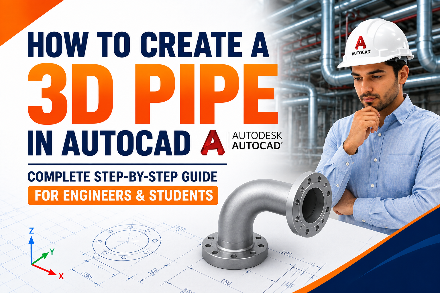
How to Create 3D Pipes in AutoCAD: A Step-by-Step Guide for Engineers
How to Create a 3D Pipe in AutoCAD: Complete Step-by-Step Guide for Engineers & Students
If you've ever tried to model a pipe network in AutoCAD and ended up with something that looks more like a bent noodle than a functioning pipeline, you're not alone. Most AutoCAD tutorials stop at flat, 2D pipe symbols — lines with a couple of parallel offsets — and never actually show you how to build a pipe that exists in three dimensions, with the right diameter, wall thickness, and fittings.
That gap matters. Whether you're a civil engineering student, a mechanical design trainee, or a working draftsman preparing shop drawings, clients and employers increasingly expect 3D deliverables, not flat schematics. This guide walks you through exactly how to model pipes in 3D AutoCAD, which commands actually work for piping (and which ones waste your time), and how to avoid the mistakes that make 90% of beginner pipe models look wrong.
New to AutoCAD altogether? Get the fundamentals right first with our Learn the basics of 2D pipe design in AutoCAD before moving into 3D modeling. then come back here to build on it in 3D.
1. Why 2D Pipe Drawings Aren't Enough Anymore
A 2D pipe drawing tells you where a pipe goes on a plan. It doesn't tell you how it clashes with a beam, whether it clears a duct, or what it looks like from an isometric view for fabrication. In real projects, plumbing layouts, HVAC piping, and process piping in a plant clash, and detection and spatial accuracy matter, and you only get that in 3D.
This is also where the industry itself is moving. MEP coordination, structural clash checks, and BIM-based project delivery all assume a 3D starting point. If your only skill is flat 2D piping, you'll hit a ceiling fairly quickly once you're working alongside Revit MEP teams or plant designers who expect a true 3D model to coordinate against.
2. AutoCAD Tools You Actually Need for 3D Pipe Design
Plain AutoCAD doesn't have a dedicated "pipe" object the way Plant 3D does, but you can build accurate, dimensionally correct pipe geometry using a small set of core 3D tools:
Polyline (PLINE): to define the pipe's centreline/path
Circle: to define the pipe's cross-section (outer diameter)
Sweep (SWEEP): the command that actually extrudes your circular cross-section along the polyline path — this is the one most tutorials skip
Extrude (EXTRUDE): useful for straight pipe runs
Fillet (3D FILLET) / Elbow blocks: for creating bends and elbows
Shell command: to hollow out a solid pipe and simulate wall thickness
If you're only modelling a handful of straight runs, Extrude is enough. The moment your pipe run has bends, Sweep is non-negotiable — it's the command that lets a circular profile follow a curved or angled path without distorting it.
3. Step-by-Step: Modeling a 3D Pipe in AutoCAD
Here's the workflow that consistently produces clean, editable pipe geometry:
Step 1 — Set up your workspace. Switch to the 3D modelling workspace (workspace switch icon, bottom right) so you have access to solid modelling tools and a proper 3D view (View > SE Isometric is a good default).
Step 2 — Draw the pipe centreline. Use PLINE to sketch the pipe's path in 3D space. For a simple run, you can draw it in plan and then use elevation changes (typing relative Z-coordinates) to route it vertically where needed.
Step 3 — Create the cross-section. At the starting point of your polyline, draw a CIRCLE perpendicular to the path, sized to your pipe's outer diameter (e.g., 150 mm for a standard process pipe).
Step 4 — Sweep the circle along the path. Type SWEEP, select the circle as the object to sweep, then select the polyline as the path. AutoCAD will generate a solid 3D pipe following the exact route you drew.
Step 5 — Hollow it out. If you need a realistic pipe (not a solid rod), use the SOLIDEDIT command with the Shell option to hollow the pipe and apply a wall thickness.
Step 6 — Apply a material (optional but recommended). Use the Materials Browser to apply a steel, PVC, or copper finish. This isn't just cosmetic — it helps clients and reviewers instantly identify pipe specification during a walkthrough or rendered view.
Want to practise this workflow with an instructor watching your model, not just a video? S2B's AutoCAD training programs walk you through real piping projects step by step, with feedback on exactly the kind of geometry errors covered in this guide.
Watch 3D Pipe Design in AutoCAD – Practical Demo
4. Adding Fittings, Elbows, and Tees
This is where most beginner models fall apart — pipes that just "stop" at a corner instead of connecting cleanly.
Elbows/bends: Instead of a sharp polyline corner, insert a fillet radius at the bend before sweeping, or use pre-built elbow blocks from AutoCAD's mechanical/piping content libraries if available in your version.
Tees and junctions: Model these as separate solid pieces and use the UNION command to merge them cleanly with the main pipe run — never leave overlapping, unmerged geometry.
Flanges: A simple extruded ring at connection points adds realism and is expected in fabrication-ready drawings.
Practical example: During AutoCAD training sessions at S2B School of Engineering, students commonly face challenges in creating realistic pipe bends and connections. Practizing sweep-based workflows helps learners create cleaner and more industry-orientated models. A batch of trainees modelling a factory's cooling-water line initially left every elbow as a raw 90-degree corner. Once we introduced filleted bends before the sweep operation, the entire model went from looking like a diagram to looking like an actual constructible pipe run — and it's the single change that most improved their portfolio pieces.
5. Comparison: AutoCAD vs Plant 3D vs SolidWorks for Piping
Feature | Plain AutoCAD | AutoCAD Plant 3D | SolidWorks |
Learning curve | Moderate | Steep | Steep |
Dedicated pipe objects | No (manual solid modeling) | Yes (parametric piping) | Yes (via routing add-in) |
Best for | Simple runs, learning fundamentals, small projects | Full plant/process piping with P&ID integration | Mechanical assemblies, product-level piping |
Cost/access | Included in standard AutoCAD | Higher-tier Autodesk subscription | Separate license |
Ideal user | Students, general drafters, freelancers | Process/plant engineers | Mechanical design engineers |
6. Pros and Cons of Modeling Pipes in Plain AutoCAD
Pros
No extra software cost — works within your existing AutoCAD licence
Full control over geometry, useful for learning how solid modeling actually works
Flexible for small-to-mid scale projects (plumbing layouts, small facility piping)
Directly transferable skill — the Sweep/Extrude logic applies to any 3D solid, not just pipes
Cons
No automatic clash detection between pipes and other systems
No built-in pipe specification database (you size everything manually)
Time-consuming for large or complex plant piping networks
No native isometric spool generation for fabrication (you'd build these manually)
7. Expert Tips for Cleaner Pipe Models
Always draw your centreline first, then build geometry around it. It keeps your pipe route editable — if the layout changes, you edit the polyline instead of rebuilding the whole model.
Use construction layers. Keep centrelines, cross-sections, and finished solids on separate layers so you can hide clutter while checking your model.
Check wall thickness against real pipe schedules (e.g., Schedule 40 steel pipe) rather than guessing — this is a common gap between "student work" and "job-ready work".
Save reusable elbow and flange blocks. Once you've modelled a clean 90-degree elbow, save it as a block. You'll reuse it constantly and save hours on repeat projects.
8. Common Mistakes Beginners Make
Sweeping a circle that isn't perpendicular to the path — this produces a distorted, oval-shaped pipe instead of a clean cylindrical one.
Skipping the Shell step and submitting a solid rod instead of a hollow pipe when wall thickness actually matters for the deliverable.
Leaving gaps at joints because fittings weren't unioned with the main pipe body.
Ignoring real-world pipe sizing standards, which makes a drawing look plausible but fail a technical review.
Modelling in 2D first and trying to "extrude up" later instead of thinking in 3D from the start — this almost always creates rework.
9. Difference Between 2D and 3D Pipe Design in AutoCAD
Feature | 2D Pipe Design | 3D Pipe Design |
View | Flat drawing | 3D realistic model |
Dimensions | Length & width | Length, width & height |
Pipe Representation | Lines and symbols | Actual pipe geometry |
Fittings | 2D symbols | Elbows, tees, flanges |
Coordination | Limited | Better clash identification |
Usage | Basic layouts | BIM, fabrication & industrial projects |
2D and 3D pipe design in AutoCAD serve different purposes in engineering projects. While 2D pipe drawings are mainly used for layout planning and documentation, 3D pipe modeling helps engineers visualise complete piping systems with accurate dimensions, fittings, and spatial coordination.
2D Pipe Design in AutoCAD
2D pipe design focuses on creating flat drawings that represent the location, size, and routing of pipes on a single plane. Engineers and draftsmen commonly use 2D pipe layouts for basic planning, annotations, and construction documentation — see our 2D pipe design in AutoCAD guide if you want to start there first.
Key features of 2D pipe design:
Shows pipe routes using lines, symbols, and dimensions
Useful for floor plans, plumbing layouts, and basic engineering drawings
Easier to create and modify for simple projects
Requires less processing power and software knowledge
Commonly used as the starting point for engineering drafting
However, 2D drawings have limitations because they do not provide a complete view of pipe elevation, spatial arrangement, or possible clashes with other systems.
3D Pipe Design in AutoCAD
3D pipe design creates a realistic digital model of a piping system with depth, height, diameter, fittings, and connections. Instead of representing pipes as simple lines, 3D modeling creates actual pipe geometry that can be viewed from different angles.
Key features of 3D pipe design:
Creates realistic pipe models with diameter and wall thickness
Helps visualize elbows, tees, flanges, and fittings
Supports isometric views and better project presentations
Helps identify routing issues before construction
Provides a foundation for BIM workflows and advanced tools like AutoCAD Plant 3D and Revit MEP
2D vs 3D Pipe Design: Which One Should You Learn?
For beginners and basic drafting requirements, 2D pipe design is an essential starting point because it builds fundamental skills in layouts, dimensions, and engineering drawings.
For professionals working on complex projects, 3D pipe modeling provides better visualization, coordination, and industry-ready skills. Learning 3D pipe design in AutoCAD can help engineers transition toward advanced workflows such as Plant 3D, BIM coordination, and Revit MEP piping.
If you already understand 2D pipe drafting, the next step is learning how to create 3D pipes in AutoCAD using tools like Sweep, Extrude, and solid modeling commands — which is exactly what the rest of this guide covers.
This is also where the industry itself is moving: MEP coordination, structural clash checks, and BIM-based project delivery all assume a 3D starting point. If your only skill is flat 2D piping, you'll hit a ceiling fairly quickly once you're working alongside Revit MEP teams or plant designers who expect a true 3D model to coordinate against.
10. Career Opportunities After Learning Plant 3D / Piping Design
Piping and plant design skills open doors across a genuinely wide range of industries — this isn't a niche skill with one job title attached to it.
Common job roles:
Piping Design Engineer / Piping Draftsman
Plant 3D Modeler / Plant Design Engineer
Mechanical CAD Designer (piping focus)
BIM Coordinator (piping/MEP discipline)
Process/Piping Layout Engineer
Isometric Drafter
Typical career path: Most people start as a junior draughtsman or CAD designer, working under a senior piping engineer on modelling and isometric generation. With 2–4 years of experience and stronger P&ID and specification knowledge, the natural progression is into a piping design engineer or plant 3D lead role and eventually into piping/plant design team leadership or BIM coordination roles that sit across disciplines.
Industries hiring for these skills:
Oil & gas and petrochemical
Chemical and process manufacturing
Power and energy (including renewable energy plants)
Water treatment and utilities
EPC (Engineering, Procurement, Construction) contractors
Pharmaceutical and food processing plants (both have significant process piping needs)
Required skills employers actually look for: AutoCAD fundamentals, Plant 3D or equivalent piping tool proficiency, P&ID reading and interpretation, awareness of piping codes and specifications (e.g., ASME B31.3 for process piping), and increasingly, basic BIM coordination exposure since plant projects are moving toward multi-discipline coordinated models.
Future growth outlook: As more EPC and process industries shift toward BIM-coordinated plant design (rather than isolated 2D/3D piping models), professionals who combine piping fundamentals with BIM coordination skills are positioned ahead of those with piping skills alone. This is part of why we link this decision back to Revit MEP in our cluster content — the two skill sets increasingly overlap in real project workflows.
11. Salary After Learning AutoCAD Plant 3D
Experience Level | India Salary Range (Annual) | Typical Role |
Entry-level (0–2 years) | ₹2.4 LPA – ₹4.5 LPA | Junior Piping Draftsman / CAD Designer |
Mid-level (2–5 years) | ₹4.5 LPA – ₹8 LPA | Piping Design Engineer / Plant 3D Modeler |
Experienced (5+ years) | ₹8 LPA – ₹15+ LPA | Senior Piping Engineer / Plant Design Lead / BIM Coordinator |
Salaries vary significantly based on your specific skill set, the hiring company, your experience level, project exposure, and your work location — figures above are general market indicators. not guarantees, and are worth cross-checking against current job listings in your target city before making a decision.
12. Skills You'll Gain From This Learning Path
After working through plain AutoCAD, 3D pipe modelling, and Plant 3D fundamentals, learners typically walk away with:
Technical Skills
Solid modeling logic (Sweep, shell, and Union) and parametric piping workflows
Reading and applying piping specifications and schedules
P&ID interpretation and how it drives 3D model creation
Software Skills
AutoCAD 3D modeling
AutoCAD Plant 3D (parametric piping, spec-driven design, isometric generation)
Working familiarity with how Plant 3D output connects to Revit MEP and Navisworks workflows
Industry Skills
Understanding plant layout and process piping conventions
Awareness of relevant piping codes and industry standards
Coordination thinking — spotting clashes and routing conflicts before they become field issues
Job-Ready Skills
Building a portfolio project that demonstrates end-to-end piping design, not just isolated commands
Communicating design decisions the way a piping engineer would justify them to a reviewer or client
13. Summary and Next Steps
3D pipe design in AutoCAD isn't about knowing more commands — it's about understanding a workflow: centreline first, cross-section second, sweep to generate the solid, then shell and detail. Once that sequence clicks, elbows, tees, and full pipe networks stop being intimidating.
If you're working on small-to-mid-scale piping, plain AutoCAD is genuinely enough. If you're heading toward plant-scale or process piping professionally, this workflow is still the right foundation before you move into Plant 3D or a full BIM environment like Revit MEP.
Ready to go beyond tutorials? S2B School of Engineering's hands-on AutoCAD, BIM, and Revit MEP training programmes are built around real project workflows like the one above — not just isolated commands. Explore our Revit & BIM training or check out our Executive Diploma in BIM to take this from a tutorial skill to a job-ready one.
FAQ SECTION
1. Can you draw 3D pipes in plain AutoCAD, or do I need Plant 3D? Yes, plain AutoCAD can produce accurate 3D pipe models using the Sweep and Shell commands. Plant 3D adds parametric pipe objects and P&ID integration, which is useful for large plant-scale projects but isn't required for learning or for small-to-mid-scale piping work.
2. What is the best AutoCAD command for modelling a pipe in 3D? Sweep is the core command — it extrudes a circular cross-section along a path (your pipe's centreline), which is what actually produces a realistic pipe shape, especially around bends.
3. Why does my swept pipe look distorted or oval-shaped? This almost always happens when the circle profile isn't drawn perpendicular to the path before sweeping. Align the cross-section to the path's starting direction before running the Sweep command.
4. How do I make a hollow pipe instead of a solid rod in AutoCAD? After sweeping your solid, use the SOLIDEDIT command with the Shell option to hollow it out and define a wall thickness.
5. What's the difference between 2D and 3D pipe design in AutoCAD? 2D pipe design shows the pipe's path and symbol on a flat plan — useful for basic layouts. 3D pipe design creates an actual solid model with diameter, height, and routing in space, which is necessary for clash detection and fabrication drawings.
6. Is AutoCAD good enough for professional piping design, or should I learn Plant 3D or SolidWorks? For small facility piping, plumbing layouts, or learning fundamentals, AutoCAD is genuinely sufficient. For plant-scale process piping with full P&ID integration, or mechanical assemblies, Plant 3D or SolidWorks, respectively, are the industry standards.
7. How do I add elbows and fittings to a 3D pipe in AutoCAD? Model bends using a fillet radius on your centreline before sweeping, and build fittings like tees and flanges as separate solids that you merge into the main pipe using the UNION command.
8. What pipe diameter and wall thickness should I use for a realistic model? Reference real-world pipe schedules (such as Schedule 40 steel pipe sizing charts) rather than arbitrary dimensions — this is a key difference between student-level and job-ready drawings.
9. Can AutoCAD 3D pipe models be used for clash detection with structural or MEP elements? Not automatically — plain AutoCAD doesn't have built-in clash detection like Revit or Plant 3D. You can still visually cross-check your pipe routing against structural and MEP geometry in the same 3D view, but automated clash reports require a BIM tool.
10. Do I need to learn Revit MEP after learning pipe design in AutoCAD? Not immediately, but it's a natural next step if you want to work in BIM-based MEP coordination, since the underlying spatial and system-thinking skills transfer directly from AutoCAD pipe modelling to Revit MEP piping systems.
Conclusion
Ready to Build Your Career in AutoCAD, Plant 3D & BIM Design?
Learn industry-focused AutoCAD, Plant 3D, and BIM skills through hands-on projects, expert guidance, certification, and placement support at S2B School of Engineering.
Start your AutoCAD & BIM learning journey today →
Contact S2B School of Engineering and take your first step towards a successful design career.